|
|
| We Accept | ||
|
|
|
|
|
Home
|

|
Email: superlumination@cox.net |
Remote Controls and Remote Switches
|
|
|
|
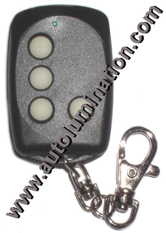
Operation & Programming Instructions for the LRT1 Programmable Remote
This programmable remote control (
remote) can duplicate a majority of fixed code remote controls.
A fixed code remote control is one that transmits the same frequency, or code each time the button is pressed.
This unit can duplicate the frequency as long as the original remote control operates between the frequencies of 251-538 Mhz and the remote does not utilize Code Hopping or Anti-Code Grabbing Technology, which changes frequency each time the button is pressed.
It is not possible to copy any remote that utilizes Code Hopping or Anti-Code Grabbing Technology. This is because these types of remotes send a different code each time the remote is pressed.
The
remote has four buttons that can each be used for multiple functions. The same code can be copied onto multiple buttons if desired. Alternatively, you can program the remote with a different code for some or each button to operate multiple devices from one remote. If your original remote has a function controlled by pressing multiple buttons together, you must duplicate that code to a single button on your
remote. You can also copy multiple remotes onto the one
remote, provided they all operate on the same frequency
PROCEDURE TO AUTOMATICALLY DUPLICATE THE CODE OF YOUR REMOTE
1. Please note that the frequency of this remote has already been set at the factory to the exact frequency that you specified when you placed your order. It is not necessary to set or adjust the frequency on this unit, however the frequency can be adjusted by following the instructions here: http://lrt1_programming_instructions.htm
Note: If the factory set frequency is altered or tampered with and set improperly, the unit may not learn, or may not transmit the proper signal or range to operate your remote controlled device. Do not adjust the FTC screw or tamper with jumpers 1 and 2 unless you intenf to alter the frequency.
If you cannot find the frequency of your unit, you may have to contact the manufacturer to determine the frequency that the remote control unit operates at.
You can also try the trial and error method, but that can be very time consuming since the programming usually requires several tries to be successful.
Note:
2.
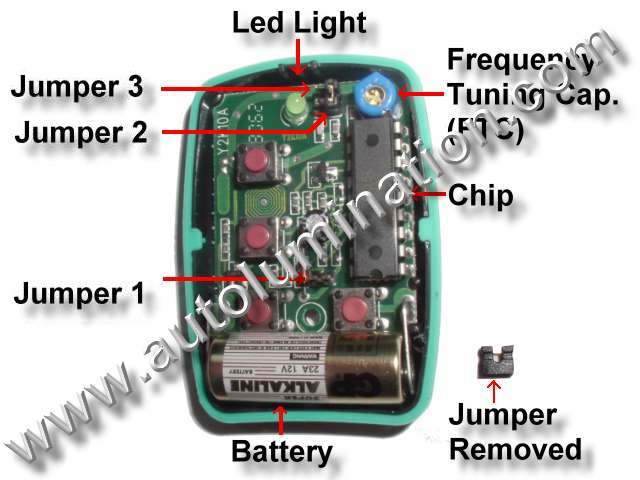
Check the position of each of the three jumper locations in the
remote after removing the cover of the
remote
.
The cover can easily be removed by pulling the two halves of the plastic case apart. Use the tool provided to pry in between parting lines to help separate the two halves of the plastic case.
There are 3 jumper locations and two plastic jumpers in each
remote
.
The jumpers can be removed or installed onto the jumper pins with a pair of needle nose pliers or tweezers.
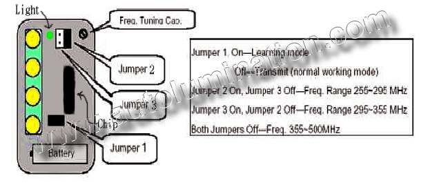
Arrange the jumpers to match the table shown below.
Jumper location 1 On – Learning Mode
Jumper location 1 Off – Transmit (normal working mode)
(Note the
remote will not transmit in learning mode and will not program in operating mode):
|
Frequency Range |
Jumper 1 |
Jumper 2 |
Jumper 3 |
|
251~294 MHz |
On |
On |
Off |
|
295-355 MHz |
On |
Off |
On |
|
355-538 MHz |
On |
Off |
Off |
|
|
3.
Place the
remote and original transmitter right next to one another on a flat non-metallic surface, or back to back in one hand.
4. Once you have the units arranged so the chips are as close to one another as possible, press & hold down the button on the original remote that you wish to program onto button 1 of the
remote, and then immediately press & hold down the button on the remote that you want to program. The green
remote light should light up green briefly and then go dark briefly.
Hold both buttons down until you see the green light on the
remote pulse three times.
This should only take ~ 5-10 seconds.
If you do not see the three pulses, you have not successfully duplicated the code from the original remote.
In some cases, this may take several tries before the code will be recognized and stored onto the
remote
.
If you do not see the green light pulse three times, repeat step 4 until the green light pulses 3 times.
Steps to take if you cannot get the green light on the remote to pulse three times after repeated attempts:
A. Ensure that the chip side of the remote is arranged so that it is as close to the original remote as possible. Ensure that the original remote is arranged so that the chip in the original remote is as close as possible to the remote chip Rotate one or both units to get the chips physically as close as possible .
B. If the green light on the remote will not light at all, check to ensure the battery is in and that the battery is not backwards (+ should be towards the buttons on the remote).
C. Ensure that the jumpers are all correct (see step 2).
5. Repeat steps 1-4 for buttons 2, 3, & 4 on the remote if desired.
Note: After all of the buttons have been programmed, the unit will not yet transmit a signal, and it will not operate properly until step 6 is completed.
6.
Remove Jumper 1 near the battery. This activates the unit and it is now in normal working mode.
The
remote now will not be reprogrammed and the remote will now transmit and operate.
CAUTION: DO NOT LOSE THE JUMPERS.
Place the unused jumpers over just one pin so you will not lose the jumpers. Alternatively, you can leave the jumpers loose inside the remote.
You may need the jumpers again someday, if you have to reprogram the
remote.
As long as the jumper is only installed over a single pin at the jumper position, it will not activate that jumper position and can be stored there safely for future use, if required.
7. After you verify that the remote operates properly for each device you have programmed it for, replace the cover and screw closed using the tool and screw provided. Do not over tighten. The procedure is now completed.
FCC Caution:
This device complies with part 15 of the FCC Rules. This operation is subject to the following two conditions. (1) This device may not cause harmful interference and (2) this device must not accept an interference that may cause undesired operation.
Note: If you get the remote light to pulse 3 times, but the remote will still not operate your device, or if the range of the remote in not sufficient, you may have to complete the following additional adjustments (First verify that jumper 1 has been removed. The remote will not transmit if jumper one is across both pins) :
TO MANUALLY ADJUST THE remote AND FINE TUNE THE FREQUENCY, FOLLOW THESE STEPS
1. Re-open the case of the remote using the tool provided. Replace Jumper 1 (Learn Mode).
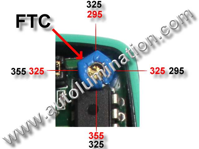
2. Identify the frequency tuning capacitor (FTC). Refer to diagram.
 .
.
3. Place the remotes together with the chips as close as possible. Press and hold down a matching button on each remote using two fingers from one hand (with a little practice you can do this yourself, or you may need a helper). Now part your fingers so as to slowly increase the distance between the remotes to the point where the green remote light becomes most dim, but is still visibly lit. As you do this, you may notice that the remote reprograms itself. After it reprograms itself (as indicated by the 3 pulses), the light will stay lit solid for only a few seconds. During this brief period,
Use the tool provided to turn the screw in the FTC very slowly clockwise and then counterclockwise until the green light on the remote glows brightest.
Once the FTC is adjusted to make the light as bright as possible, you have maximized the range of the remote for that device.
During this process, you may notice that the remote will not reprogram, or loses it's program. This is caused by the FTC being adjusted too much or in the wrong direction. To correct, place the units
|
|
The FTC will change the frequency at a rate of +/-60 mhz for each 1/2 revolution, so it is very sensitive. Usually the frequency only is off about 10 mhz, so you may only need to move the FTC 1/8 turn one direction or the other to move 10 mhz.
Examples:
For frequency range 295-355, if you turn the FTC 180 degrees (1/2 turn in either direction) it will move +/-60 mhz, so if it was at 295 mhz and you turn it 180 degrees it will go to 355 mhz.
If it was at 325mhz and you turn it 180 degrees (1/2 turn), it will be at 325 mhz.
If you turn the FTC 90 degrees it will change the frequency ~+/-30 mhz. If you rotate the FTC 360 degrees, it will return back to the original frequency.
IMPORTANT: After this process, be sure to remove Jumper 1 before trying to operate the remote. The remote will not transmit if Jumper 1 on both pins.
4. If you do not know the frequency range of your remote, try another Frequency Range by changing configuration of Jumper 2 & 3 and repeat the programming steps .
|
Frequency Range |
Jumper 1 |
Jumper 2 |
Jumper 3 |
|
251~295 MHz |
On |
On |
Off |
|
295-355 MHz |
On |
Off |
On |
|
355-538 MHz |
On |
Off |
Off |
5. Once successful, operating range can be maximized by moving to the furthest distance from the remote controlled device where the remote signal will still make the remote controlled device function. Take two steps backwards and minutely adjust the FTC in either direction until the alarm arms again. Repeat this procedure until maximum range is achieved.
6. Replace the case and screw it closed. Do not over tighten. The procedure is now complete.

Standard Rates (US Only)
*Via US Postal First Class Mail
* Orders weighing more than 1 lb will ship via parcel post unless special shipping options are added (below).
Shipping & Handling
|
Total Order |
Cost |
| $.01-$9.99 | $3.50 |
| $10.00-$49.99 | $4.00 |
| $50.00-$99.99 | $5.00 |
| $100-$199.99 | $10.00 |
| $200+ | $15.00 |
*Note: If you do not add any special shipping options to your order, we will automatically ship via US postal first class mail.
You must choose a special shipping option (see below) in order to get a tracking number.
***Click Here to add a tracking number to your order***
All International orders must choose an international shipping option.
![]()
![]()
![]()

UPIC Shipping Insurance
Note: Our packages are not automatically insured against loss during shipping. Insurance is the responsibility of the purchaser!
$2.00 for each $100 unit of insurance
Shipping Insurance
$2.00 per $100
|
Powered by Ewebmerchant.com |
remocon lrt-1 Y2K